In this post we will take a look how to update firmware for ESP 12-E module.
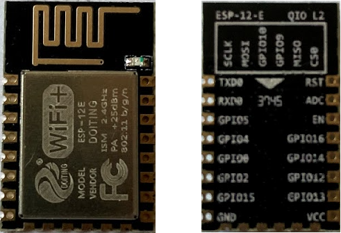
ESP 12-E WiFI moduleWe will need “Flash Download Tools” program that you can find here: https://www.espressif.com/en/support/download/other-tools
And we will also need new firmware, i have used “NONOS SDK 2.2.1” version that you can get here: https://github.com/espressif/ESP8266_NONOS_SDK/releases/tag/v2.2.1
Normal mode
For the normal usage of this module together with Arduino we have to connect:
– Vcc to 3.3v (you should have external 3.3v power supply because ESP needs lots of current)
– GND to GND
– EN pull up
– GPIO 15 pull down
– TX to Arduino RX
– RX to Arduino TX
Boot mode
To be able to upload new firmware to ESP we need to start it in the correct mode.
This mode should be UART Bootloader mode.
To do this, we need to leave the EN pin pulled up and GPIO 15 pulled down and then we need to pull down GPIO 00 and pull up GPIO 02 (it also works if we don’t connect GPIO 02, since it is detected as HIGH if not connected (its more for stability reasons to pull it up)).
If you are using PCB adapter for ESP module, the one that you see on the image belowe, then the GPIO 15 is already pulled down and EN pin is already pulled up, by the 10K Ohm resistors that you can see on the bottom of the adapter.
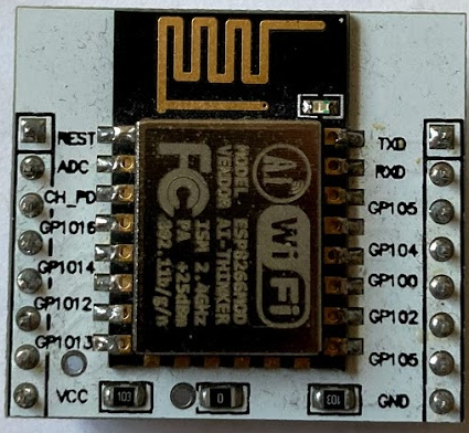
PCB adapter for ESP8266Uploading firmware
For uploading new firmware from our computer to ESP we will use FTDI USB 3.3V Serial Adapter.
ESP module is only 3.3V compatible, so make sure that you have FTDI adapter that supports 3.3V.
The one on the bottom picture has option for 5V or for 3.3V, so make sure that you have jumper set to 3.3V.
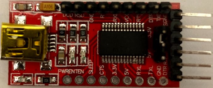
FTDI USB 3.3V Serial AdapterOn the bottom picture you can see how to wire up the FTDI adapter with ESP for starting it into boot mode.
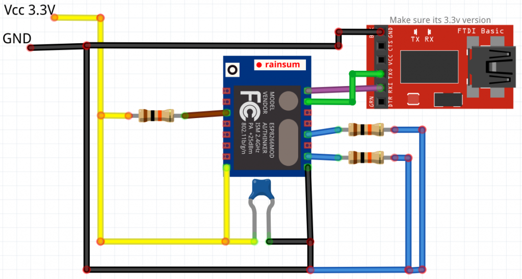
Wiring for uploading firmware to ESP8266 with FTDI adapterConnect FTDI adapter to computer then open Arduino IDE and under the “Tools” menu select proper “Port” and then open serial monitor that you also find in the “Tools” menu.
Then select baud 74880 to see “debugging” messages from ESP module. This way we will see it ESP started in the proper boot mode. Now that we setup our serial monitor, restart ESP module (you can just disconect GND and then reconnect it). If ESP is in the correct mode for uploading, then you should see somthing like on the following picture.
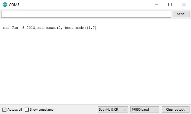
ESP startup boot mode messageNow lets close serial monitor and open “Flash Download Tools” program and setup the configuration like you see on the photo below.
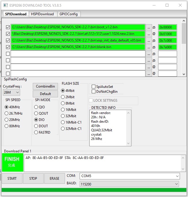
Addresses and other settings for uploading new firmware to ESP 12-EAfter you fill in all the settings press start and waint to see “FINISH” text.
Now that new firmware is uploaded lets test what version is installed by sending AT+GMR command to ESP module.
Open serial monitor and set baud to 115200, disconnect pull down from GPIO 00 so that we have wiring for normal operation and restart the ESP module. After restarting, I get some weird symbols and then in the new line text “ready”. Now write AT+GMR press enter and you should get back text telling you which version is running.
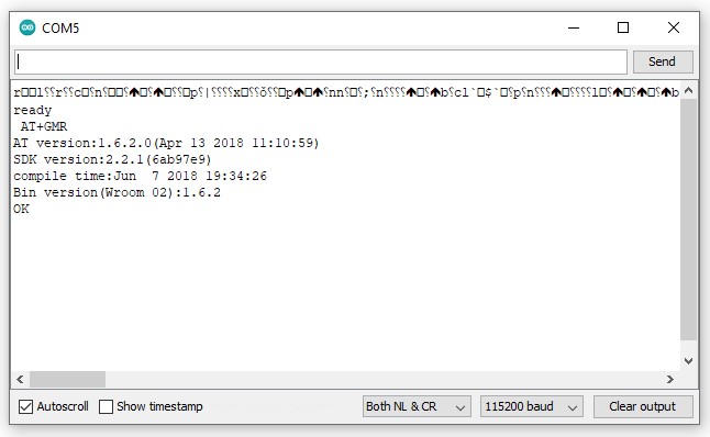
AT+GMR command responseMore info:
http://arduino.esp8266.com/Arduino/versions/2.3.0/doc/boards.html
https://robertoostenveld.nl/esp8266-at-firmware